False Car Platform: What The Detail Actually Decides
Two false car platform units can look identical in a photograph and behave completely differently in a shaft. The differences sit in the parts nobody photographs: how the gauge adjustment locks, how thick the deck is, where the anti-derailment switch is wired, and whether the safety tongs can be set from the working position.
This article goes through the platform itself — not the hoist, not the lock — and explains what each detail decides. Reference data comes from the FC400 and FC1000 platforms built by RIGID CO., LTD. (Wuxi Rigid Machinery) in Wuxi, Jiangsu, China.
The Platform Is the Interface
A
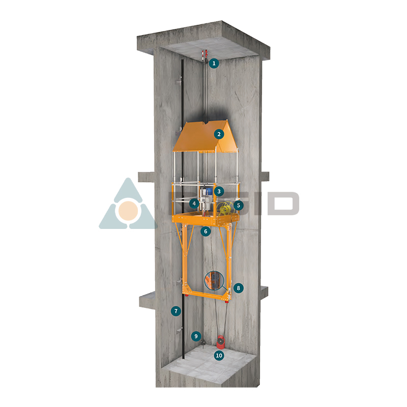
false car platform sits between four systems: the hoist that lifts it, the safety lock that arrests it, the guide rails that locate it, and the people who work from it. Every one of those connections is made through the platform structure.
That is why the platform, rather than the hoist, is usually the limiting component. A 2000kg climber bolted to a 400kg platform gives you a 400kg system.
Gauge Adjustment: The Function That Decides Coverage
Two Directions, Not One
Shaft dimensions vary in two axes. The rail gauge — the distance between the guide rail centrelines, often written DBG — varies across the shaft. The clear distance between the rails varies along it.
A platform that adjusts in only one direction will fit some shafts and not others, and the fitter discovers this at the landing rather than at the quotation stage. Both RIGID platforms adjust in both directions, with independent extension ranges.
Why the Ranges Overlap
The FC400 range covers 1200–2000mm, 1500–2600mm and 1700–3000mm of rail spacing across three models, with a 1500–2000mm platform extension on all three. The FC1000 covers 1500–2100mm and 2100–2700mm of rail spacing with 1440–2040mm and 2040–2640mm extension.
The overlap between models is deliberate: a shaft that sits near a boundary can be served by either of two models, and the choice then falls to load and process rather than to geometry.
|
Model |
Rated load |
Rail spacing (DBG) |
Platform extension |
Weight |
|
FC400-A20 |
400kg |
1200–2000mm |
1500–2000mm |
150kg |
|
FC400-A26 |
400kg |
1500–2600mm |
1500–2000mm |
170kg |
|
FC400-A30 |
400kg |
1700–3000mm |
1500–2000mm |
200kg |
|
FC1000-S21 |
1000kg |
1500–2100mm |
1440–2040mm |
390kg |
|
FC1000-S27 |
1000kg |
2100–2700mm |
2040–2640mm |
460kg |
The Locking Detail
An adjustable platform that creeps under load is worse than a fixed one. The extension has to be positively locked, not clamped by friction alone, and the lock has to be inspectable — a fitter should be able to see at a glance whether both sides are engaged.
The Deck
The working floor is timber on a metal frame, and the thickness is specified rather than left to site.
On the FC400 aluminium platform the wooden floor is at least 15mm. On the FC1000 steel platform it is at least 18mm, because the steel platform carries 1000kg and the point loads from rail sections are higher.
Thin plywood is the most common substitution made on site and the most common cause of a platform being rejected at inspection. A deck that deflects under a fitter's boot changes how the load distributes into the frame, and it hides damage underneath.
Guardrails and the Canopy
Guardrails run around the perimeter on both platform families. Their job is not only fall prevention at the platform edge; they also give the fitter something to brace against when handling a rail section, which is when most near-misses happen.
The canopy is a separate structure above the working position. The FC400 uses a timber canopy assembled to site dimensions. The FC1000 uses a high-strength steel retractable roof.
Falling objects are the dominant hazard in a shaft that is being built from the top down, and the canopy is what makes the platform usable underneath other trades.
Anti-Derailment: A Switch, Not a Bracket
Scaffoldless False Car For Elevator Cabin Installation
The anti-derailment system on a RIGID platform is a switch assembly mounted on the
platform that bears laterally against the guide rail, wired into a socket on the climber control box.
The function is a cut-out. If the platform lifts or shifts off the rail, the switch opens and the climber stops. This is not a structural restraint — it does not physically hold the platform on the rail. It removes power before the geometry gets worse.
Buyers sometimes expect the derailment protection to be a mechanical guide. It is worth being clear at the specification stage: on these platforms it is an electrical interlock, and its reliability depends on the switch being tested at every setup.
Safety Tongs and the Hammers
The safety tong assembly is the second arrest layer. It is set manually to the normally-open position before work starts; if the climber rope loses tension, the tongs close on the guide rail and hold the platform.
Two heavy hammers hang from the platform to keep the safety lock rope and the climber rope vertical. Without them the ropes can swing and the lock can see an angle it was not designed for.
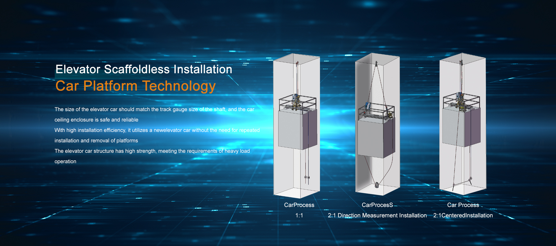
On 2:1 platforms a diverter counterweight performs the same duty for the doubled rope path and prevents the rope from wrapping on itself.
Setting Up
The order matters more than the individual steps:
1. Set the platform gauge to the shaft and confirm both extension locks are engaged
2. Fit the safety tongs to the rail and set them normally open
3. Hang the hammers and confirm both ropes hang clear
4. Confirm the deck thickness and condition
5. Test the anti-derailment switch against the climber cut-out
6. Prove the overspeed lock under load before anyone stands on the deck
Selecting a Platform
Three inputs are enough to shortlist: rail gauge range, guide rail profile and the load the
platform must carry. RIGID platforms accept T75 to T78 rails with a K=10 bracket and T89 to T127 with K=16, which covers the great majority of traction and hydraulic shafts.
RIGID builds both platform families, supplies the hoists and locks that go with them, holds TUV and SGS CE certification across the range, and provides professional training with each platform. The company has led and participated in drafting GB 40160-2021 and GB 19155-2017.
Send RIGID the shaft rail gauge, rail profile and working load at +86 510 6808 0177 for a platform recommendation.










 +86 51068080177
 Current location: