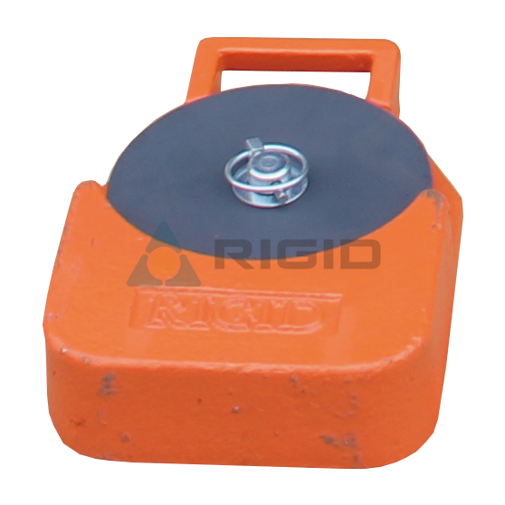
Reversing Counterweight Systems — Design, Installation, And Inspection
What Is a Reversing Counterweight System?
A reversing counterweight system places the counterweight on the car side of the shaft and routes the wire ropes around diverter sheaves so they run parallel to the car travel, eliminating the back wall of the shaft as the counterweight's travel path. It is used when the shaft geometry cannot accommodate a traditional back-wall counterweight — typically because the shaft is narrow, because the back wall is structurally weak, or because the counterweight would interfere with permanent fixtures.
In a conventional elevator, the counterweight runs in its own guide rails on the opposite side of the shaft from the car. The car and counterweight are connected by wire ropes that pass over the traction sheave in the machine room or on the car top. The two move in opposite directions during travel.
In a reversing counterweight system, the counterweight is mounted on the car side of the shaft, typically on a frame attached to the car sling or running in the same guide rails. The ropes pass around diverter sheaves at the top and bottom of the shaft, creating a "reversing" geometry. The car and counterweight move in the same direction during travel; the diverter sheaves reverse the rope's direction at each end.
When Is a Reversing Counterweight System Required?
A reversing counterweight system is required when the shaft geometry precludes a back-wall counterweight, and the alternatives are too costly to justify. The four common triggers:
|
Trigger |
Why a reversing system is chosen |
|
Narrow shaft |
Back-wall counterweight would foul the car travel |
|
Weak back wall |
Back wall cannot support the counterweight rail loads |
|
Back-wall obstruction |
Pipework, cable trays, or permanent fixtures occupy the back-wall path |
|
Low headroom |
Counterweight runs above the car, not below |
|
Modernization |
Existing shaft lacks back-wall space |
The trade-off is mechanical complexity. A reversing system uses more rope (typically 2× the shaft height per rope run), more sheaves (typically four per system: two upper, two lower), and a heavier counterweight frame. The benefit is that the shaft can be much narrower than a conventional layout would require.
What Are the Main Reversing Counterweight Configurations?
Two configurations are common: the "above car" arrangement, where the counterweight sits on top of the car, and the "beside car" arrangement, where the counterweight runs beside the car in the same guide rails. The Wuxi Rigid reversing counterweight family covers both.
|
Configuration |
Counterweight position |
Shaft width impact |
Mechanical complexity |
|
Above car |
Above the car, on the same guide rails |
Narrow shaft OK |
Two upper sheaves, one lower sheave per rope |
|
Beside car |
Beside the car, on separate guide rails |
Medium shaft OK |
Two upper, two lower sheaves per rope |
|
Beside car (shared rails) |
Beside the car, on shared rails |
Narrowest shaft |
More complex bracketry |
The above-car arrangement is the most common on installation hoists because the counterweight frame can be removed with the car once installation is complete. The beside-car arrangement is more common on permanent reversing elevators.
How Is the Counterweight Mass Sized?
Counterweight mass equals the car mass plus approximately 40–50% of the rated load, the standard elevator industry rule that minimizes motor size while maintaining adequate traction. The exact percentage depends on the duty cycle and the standard.
For a 1000 kg car with a 1000 kg rated load:
Counterweight = car mass + 0.45 × rated load = 1000 + 450 = 1450 kg.
This balance is the "ideal" empty-car condition: the motor lifts only the load, not the counterweight. The motor's required torque is minimized at this balance point.
The Wuxi Rigid reversing counterweight units are supplied with calibrated mass; the as-supplied mass is recorded on the identification plate and verified at the site with calibrated scales.
What Rope Configuration Is Used?
Reversing counterweight systems use 2:1 roping (the rope passes around a sheave on the counterweight and a sheave on the car, halving the rope tension on the traction sheave). 2:1 roping is standard because it allows the use of smaller ropes, smaller traction sheaves, and smaller motors than 1:1 roping for the same load.
|
Roping |
Rope tension at sheave |
Rope length per shaft metre |
Typical use |
|
1:1 |
Full car + counterweight load |
2 × shaft height |
Direct-acting, low-rise |
|
2:1 |
Half car + counterweight load |
4 × shaft height |
Most modern elevators |
|
4:1 |
Quarter load |
8 × shaft height |
Heavy-duty, very tall shafts |
A reversing counterweight system typically uses 2:1 roping because the rope length is already greater than 1:1 by a factor of two (the rope traverses the shaft twice), and the additional reduction from 2:1 roping keeps the sheave loads manageable.
How Are the Diverter Sheaves Sized and Positioned?
Diverter sheaves on a reversing counterweight system must be sized to the same D/d ratio as the traction sheave, must align within ±0.5 mm per metre, and must be accessible for inspection. Four sheaves are typical: two upper (at the top of the shaft), two lower (at the bottom of the shaft).
|
Sheave |
Function |
Typical diameter |
|
Upper diverter |
Redirects rope from traction sheave to counterweight |
Same as traction sheave or slightly smaller |
|
Lower diverter |
Redirects rope from counterweight to car |
Same as traction sheave or slightly smaller |
|
Deflector (where used) |
Supports rope at corners |
Typically smaller, non-load-bearing |
Each sheave's groove profile must match the rope, and each sheave's bearings must be sized for the radial load from rope tension. The Wuxi Rigid Diverter Pulley range is compatible with reversing counterweight systems and matches the Steel Wire Rope for Traction Hoist diameters.
How Is the System Installed?
Installation proceeds in five phases: shaft survey, frame installation, rope threading, sheave alignment, and commissioning. Each phase has specific checks.
Shaft survey. Verify clearances, wall straightness, plumb, and the position of any permanent fixtures. The site survey confirms that the reversing layout fits within the available geometry.
Frame installation. Mount the counterweight frame on the car sling or on the guide rails, depending on configuration. Verify plumb and alignment with a laser tool.
Rope threading. Thread the ropes through the diverter sheaves and over the traction sheave in the specified sequence. Each rope is cut to length with calibrated allowance for terminations.
Sheave alignment. Align each diverter sheave to within ±0.5 mm per metre of shaft length. Verify rope tracking in the grooves with a no-load run.
Commissioning. Test the system under no load, then under incremental load to rated capacity. Verify brake function, traction, and rope tension uniformity.
The Wuxi Rigid reversing counterweight installation manual covers each phase in detail, including the torque values for the structural bolts and the rope termination procedure.
What Are the Inspection Requirements?
Inspection covers rope condition, sheave condition, counterweight frame integrity, and rope tension uniformity — at frequencies defined by the standard and the site-specific duty cycle. A typical schedule:
|
Inspection |
Frequency |
Inspector |
|
Visual (rope, frame, sheaves) |
Daily |
Operator |
|
Rope tension measurement |
Monthly |
Trained inspector |
|
Sheave alignment check |
Quarterly |
Trained inspector |
|
Counterweight frame bolt torque |
Annually |
Trained inspector |
|
Rope retirement decision |
Per standard |
Qualified person |
Rope tension is measured with a calibrated tension gauge on each rope at a defined position. Asymmetry greater than 10% between ropes triggers re-termination of the lighter rope.
How Is Rope Tension Balanced?
Rope tension is balanced by adjusting the rope terminations until each rope carries an equal share of the counterweight load. Three methods are common:
Turnbuckle terminations. Each rope has a turnbuckle that lengthens or shortens the rope, adjusting tension. The simplest and most adjustable method.
Shim plates at the termination. Adding shims under the rope termination increases the rope's effective length and reduces tension.
Spring-loaded terminations. A spring in the termination path maintains constant tension as the rope stretches in service. Common on long-roping systems.
Rope tension is verified by plucking the rope and measuring the frequency, or by a calibrated load cell at the termination. The Wuxi Rigid installation manual specifies the target tension range for each rope diameter.
What Are the Common Failure Modes?
Five failure modes are common on
reversing counterweight systems; each is preventable by the standard inspection routine.
Unequal rope tension. One rope carries more than its share of the load; the lighter rope wears at the terminations. Preventable by monthly tension measurement and adjustment.
Sheave misalignment. A diverter sheave drifts out of alignment, accelerating rope wear. Preventable by quarterly alignment check.
Counterweight frame bolt loosening. Vibration gradually loosens the structural bolts. Preventable by annual torque verification.
Counterweight mass error. The supplied counterweight is not within 5% of the design mass. Preventable by site verification with calibrated scales.
Rope retirement deferred. The rope is kept in service past retirement thresholds. Preventable by following the standard rope retirement criteria.
Each failure mode is detectable during a routine inspection and is correctable before it causes a safety event.
How Does Wuxi Rigid Support Reversing Counterweight Selection?
Wuxi Rigid supports reversing counterweight selection with engineered units sized to the project's shaft geometry, rope diameter, and counterweight mass. The selection process:
Provide the shaft GA drawing with clearances, plumb, and any obstructions.
Provide the car mass and rated load.
Specify the standard (EN 81-20, ASME A17.1, GB 7588) for the destination country.
Wuxi Rigid returns a counterweight frame drawing, a rope and sheave schedule, and an installation sequence.
Custom designs are typical for non-standard shaft geometries; standard designs are used when the shaft matches the Wuxi Rigid reference geometry.
What Documentation Should Be Retained?
The site file should retain the engineering drawings, the counterweight mass record, the rope certificates, the sheave profile certificates, the installation records, and the inspection log over the system's service life. The documentation is the legal proof that the system was installed and maintained to the standard.
|
Document |
Purpose |
|
Engineering drawing (GA) |
Defines the geometry for installation and inspection |
|
Counterweight mass record |
Confirms the mass is within design tolerance |
|
Rope certificate |
Confirms rope specification matches the design |
|
Sheave profile certificate |
Confirms sheave groove geometry |
|
Installation record |
Documents the as-built geometry and tension |
|
Inspection log |
Records every inspection and any corrective action |
The Wuxi Rigid reversing counterweight documentation pack includes templates for each item.
Frequently Asked Questions
Q: Can a reversing counterweight system be retrofitted to an existing elevator?
A: Yes, in principle, but the modification is significant. The shaft must be re-surveyed for clearances, the traction sheave may need to be replaced to accommodate the new rope configuration, and the diverter sheaves must be installed with their supports. Most retrofits are done during a major modernization.
Q: What is the cost premium of a reversing system versus a conventional counterweight?
A: A reversing counterweight system typically costs 30–60% more than a conventional system, driven by the additional sheaves, longer ropes, and heavier counterweight frame. The premium is justified when the shaft geometry cannot accommodate a conventional layout; in other cases, a conventional layout remains the most economical.
Q: How does a reversing counterweight affect the elevator's energy consumption?
A: The additional rope weight and sheave friction increase the no-load energy consumption by 10–20% versus a conventional system. The energy consumption at rated load is similar, because the counterweight mass is the same in both configurations. The premium is a one-time capital cost, not an ongoing operating cost.
Q: Can a 4:1 roping be used with a reversing counterweight?
A: Yes, 4:1 roping can be combined with a reversing counterweight for very tall shafts or very heavy loads. The system uses more sheaves (typically eight) and significantly more rope. Wuxi Rigid can engineer a 4:1 reversing system for special projects on request.
Q: What is the inspection interval for a reversing counterweight on an installation hoist?
A: A reversing counterweight on an installation hoist typically receives a daily visual inspection by the operator, a monthly rope tension check, a quarterly alignment check, and an annual frame torque check. The rope retirement decision is made per the standard's rope retirement criteria.
Q: How is the counterweight mass verified on site?
A: The counterweight is weighed on calibrated platform scales or by a calibrated load cell integrated into the lifting slings. The mass is recorded on the as-built sheet and compared to the design value. A deviation greater than 5% requires correction.
Q: What happens if one rope in a multi-rope system is shorter than the others?
A: The shorter rope carries more than its share of the load. The asymmetry accelerates the shorter rope's wear and may cause traction issues if the asymmetry exceeds 10%. The remedy is to re-terminate the lighter rope to equalize the tensions.
Q: Are reversing counterweight systems allowed by all elevator standards?
A: Most standards accept reversing counterweight configurations, but the safety factor on the counterweight frame and the rope terminations is typically higher than for a conventional layout. The destination standard's specific requirements must be checked before specifying the system.
Conclusion
A reversing counterweight system is the correct solution when the shaft geometry precludes a conventional back-wall counterweight. Wuxi Rigid Machinery supplies reversing counterweight units engineered for this duty, paired with Steel Wire Rope for Traction Hoist and Diverter Pulley components matched to the system's rope diameter and tension. Correct sizing of the counterweight mass, careful alignment of the diverter sheaves, and disciplined inspection are the foundations of a safe reversing system. Pair the counterweight selection with the LTD200 traction hoist and the Authentication certificates for the destination standard.










 +86 51068080177



 Current location:Home
>News
>Industry news
Reversing Counterweight Systems — Design, Installation, And Inspection
Current location:Home
>News
>Industry news
Reversing Counterweight Systems — Design, Installation, And Inspection